


Generar topología de red
Generar topología de red
This utility creates a topology for the input layer being used. The input layer has to be a line layer and it is necessary to first create a topology before routes can be calculated using the network.
- From the Network menu select Generate network topology.
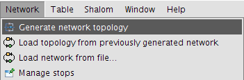
Generate network topology for the line layer
- This displays a wizard that guides the user through the process of building the topology.
Calcular la red sobre la capa original
If this is the first time that the layer is being used for network analysis then this option must be selected in order to generate the layer's topology.
- Select the option Compute the network over the original layer.
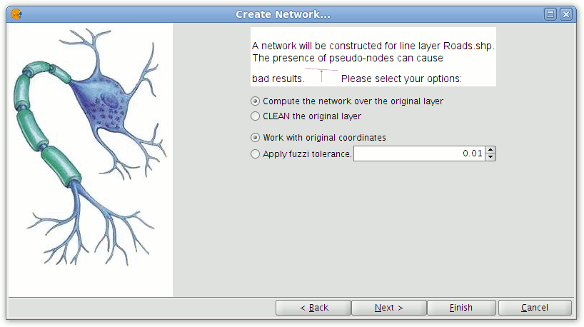
Options for generating the network topology
- Click Next.
In the second window of the wizard attribute fields containing values for the following parameters can be selected (these fields must be defined as numeric):
- Type of route: Indicates what type of route each segment is.
- Length: The length of each segment in metres.
- Cost: Indicates the cost of traversing each segment.
- Conversion factor: Factor to convert the cost field.
- Direction field: The field containing the segment direction.
- Digitised direction: Value indicating the direction of digitising.
- Reverse digitised direction: Value indicating the opposite direction of digitising.
- Save .net file: The directory and file for saving the topology.
NOTE: Any values other than those indicated in the Digitised direction and Reverse digitised direction settings will be taken to indicate flow in both directions along a segment.
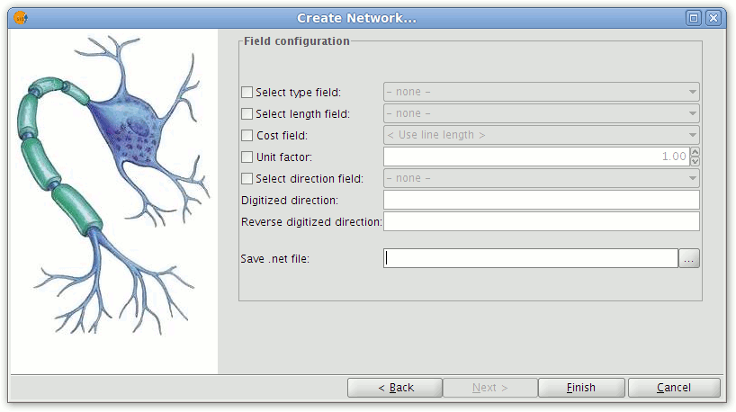
Dialog for configuring fields
Click the check-boxes alongside parameters that will be included in the topology generation. From the drop-down lists select the attribute fields corresponding to each parameter.
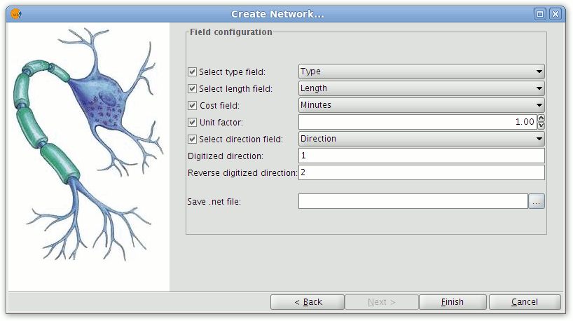
Selecting the fields that help define the network topology
Press the "Finish" button to start the generation of the topography. A window showing the progress of the operation will appear.
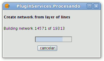
Progress of topology generation
Corregir topológicamente la capa original
This tool performs two functions. Firstly, lines are lengthened according to the specified tolerance and, secondly, nodes are inserted where two lines cross or touch.
- To topologically correct a layer select Network|Generate network topology from the menu bar.
- In the wizard select CLEAN the original layer.

Dialog showing the option for cleaning the original line layer
- Press the Next button and set the fields containing values that will be used to create the topology. Click the Finish button to complete the process.
Trabajar con las coordenadas originales
This option retains the original coordinates of the layer.
Usar tolerancia para crear topología de red
This option allows a tolerance to be defined for generating the topology. For example, if there are two segments with one of them ending at the point (0,0) and the other at (0.01, 0.02), selecting Work with original coordinates will create two nodes. However, if the Apply fuzzy tolerance option is selected and the tolerance is set to 0.02, then only one node will be created.


